Introduction
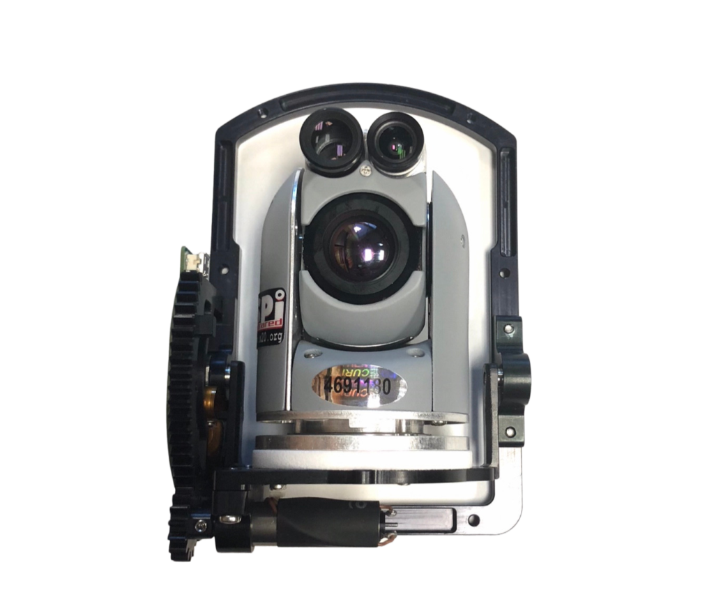
Imagine a device that’s straight out of a science fiction story, one that allows you to capture stunningly smooth and stable footage, irrespective of how much you move, jump, or even run. This fascinating piece of technology is a gimbal camera. Now, you might be wondering how it achieves such an incredible feat. So, let’s embark on a journey to demystify this technology, explaining its working in a way that everyone can understand. Later, we will delve into the more technical aspects, using mathematical descriptions.
The Basics
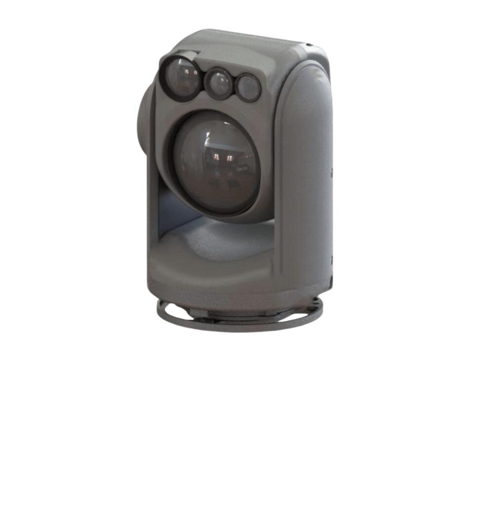
At its core, a gimbal is a pivoted support that allows rotation of an object around one or more axes. In the context of a camera, a gimbal stabilizes it against the photographer’s movements. This results in smooth and professional-looking video footage, even under less-than-ideal conditions.
The underlying principle behind gimbals is quite old and dates back to ancient times, with the earliest known gimbal found in a Greek incense burner from the 3rd century BC. However, it’s only in the last few decades, with the advancement of technology, that gimbals have become compact and affordable enough for widespread use in photography and videography.
The Science Behind It
Three-Axis Stabilization
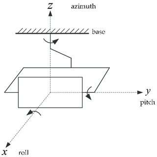
The key to a gimbal’s ability to keep the camera steady is three-axis stabilization. These three axes are the roll, pitch, and yaw.
Roll is the rotation around the front-to-back axis. Imagine nodding your head “yes” – this is roll.
Pitch is the rotation around the side-to-side axis. Think about shaking your head “no” – this is pitch.
Yaw is the rotation around the vertical axis. If you turn your head to look left or right, you’re yawing.
A three-axis gimbal will correct for unwanted movement in all three of these axes, resulting in a steady, stable shot.
Gyroscopic Sensors and Motors
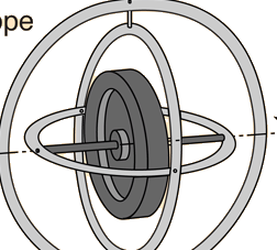
The “smart” part of a gimbal is its use of gyroscopic sensors. These sensors detect motion and measure the rate of rotation around the three axes. When the sensors detect any unwanted movement, they send a signal to the gimbal’s motors to counteract it.
The motors attached to each axis then move the camera in the opposite direction of the detected motion. This action negates the unwanted movement, keeping the camera stable. The amazing thing is that all of this happens in real-time, often hundreds of times per second.
The Role of Software
Along with the hardware, software plays a crucial role in a gimbal’s operation. Advanced algorithms interpret the data from the gyroscopic sensors and determine the best way to move the motors to counteract any detected movement. They can even learn from past movements to predict and better counteract future ones.
The Technical Side: Math and Physics
Now that we’ve explained how a gimbal works in layman’s terms, let’s delve a bit deeper into the mathematical and technical side of things.
The gyroscopic sensor measures angular velocity, often in degrees per second. This data is typically captured as a vector, representing the velocity around each of the three axes.
Let’s represent the angular velocity vector by ω = [ωx, ωy, ωz]. This vector is then fed into the control algorithm, which is often a type of Proportional-Integral-Derivative (PID) controller.
The PID controller takes an error signal – in this case, the difference between the measured angular velocity and the desired angular velocity (typically zero, as we want the camera to remain steady) – and calculates an output to correct the error.
the PID controller is a new vector, u = [ux, uy, uz], which is the command sent to the motors. Each of these three values corresponds to the amount of force the motor on each axis needs to apply to counteract the detected motion.
The PID controller uses three separate parameters: proportional, integral, and derivative values, represented by P, I, and D. These are carefully tuned for optimal performance. Here’s how they work:
Breaking It Down
The Proportional term (P) responds to the current error. If the camera is tilted 10 degrees from the desired position, the proportional response might be to push it back with a force of 10 units.
The Integral term (I) responds to past errors. If the camera was off by 5 degrees 1 second ago and by 10 degrees now, the integral response might be to push it back with a force of 15 units.
The Derivative term (D) responds to future errors, as predicted by current rate of change. If the camera is off by 10 degrees now and is moving at 5 degrees per second, the derivative response might be to push back with a force of 15 units, anticipating the position one second into the future.
Highly Adaptive
These PID controllers are calculated for each of the three axes, resulting in a highly responsive system that can adapt to changing conditions in real-time.
The force commands u = [ux, uy, uz] are then converted into electrical signals that control the gimbal motors. The motors, in turn, generate torques that oppose the undesired motion, keeping the camera stable. This is done using a feedback mechanism, meaning the system is constantly adjusting and correcting itself.
This process is repeated hundreds or even thousands of times per second, which is why a gimbal can respond to even the slightest movement. The beauty of the PID controller is that it can be tuned to respond with just the right amount of force, not too little (which would result in shaky video) and not too much (which would result in an overly stiff and unnatural look).
Conclusion
The magic of a gimbal camera lies in its combination of ancient mechanical principles with cutting-edge electronics and software. Behind the scenes, it’s a symphony of physics, mathematics, and engineering, all working together to help you capture the perfect shot. Next time you see a video with incredibly smooth footage, you’ll know a bit more about the technology that made it possible!

